Introduction
In this tutorial, we show you how to QikEasy Adapter’s Virtual Wireless Sensor feature to build a custom remote controller to wirelessly control a LEGO Race Car.

In this tutorial, we show you how to QikEasy Adapter’s Virtual Wireless Sensor feature to build a custom remote controller to wirelessly control a LEGO Race Car.
The materials we used include:
For the Race Car:
For the Remote Controller:

The actual construction design of your LEGO car do not matter much. But because our custom remote controller sends data inputs to the hub as two channels: one for forward backward, and another for steering angle, it would make the implementation of the control coding simpler if the car uses 1 motor to drive forward and backward and uses another motor for the steering angle.
Make sure the QikEasy Adapter has been configured as a Virtual Wireless Sensor. If you haven’t already done that, please follow the instructions here to perform the configuration.
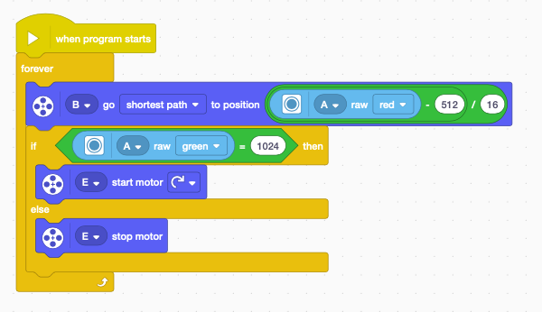
The hub has 3 devices connected to it:
This program simply sets the steering angle based on the Virtual Sensor’s red intensity. And for when Raw Green intensity equals 1024, the driving motor will start, else it will stop.
Note: This program runs on Spike App 3, you will have change the range of the Raw Red and Raw Green from (0, 1024) to (0, 255) when using Spike App 2 or Robot Inventor.
Note #2: Make sure your QikEasy Adapter has been setup to run in Virtual Wireless Sensor mode as described on this page.
Parts :
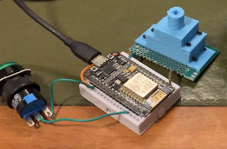
How it works:
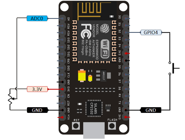
The potentiometer is used to provide variable analog voltage to the AD input (i.e. A0 pin) of the ESP8266, controlling the steering of the RC car.
A push button is used for controlling the ON/OFF state of the Rear Wheel driving motor. We connected the push button input to the GPIO4 pin of ESP8226, which is set to PULL UP internally. D2 pin When push button is pressed, it would connect the GPIO4 pin to ground.
The software is basically the firmware running on the ESP8266 device.
Notes on the Program
Make sure to install the AsyncHTTPRequest_Generic (by Bob Lemaire and Khoi Hoang ) and its dependent libraries before building this ESP8266 firmware.
The reason why we use AsyncHTTPRequest_Generic to make HTTP requests instead of the default ESP8266HTTPClient class is that when we use ESP8266HTTPClient to continuously make requests, we found that a lot of times, the requests will get stuck and that cause a long delay between requests. This is unacceptable for our application which requires close to real time responses.
http://<QIKEASY_IP_ADDR>/set?t=c&r=<Steering Value>&g=1024
Steering value ranges from 0 to 1024, where a value of 512 will align the wheel to go straight.
//****************************************************************
// Make sure to install the AsyncHTTPRequest_Generic and
// dependent libraries before building this.
//****************************************************************

#include <ESP8266WiFi.h>
#include <AsyncHTTPRequest_Generic.h>    // https://github.com/khoih-prog/AsyncHTTPRequest_Generic

#include <Ticker.h>


#define BUTTON_PIN 4
#define QIKEASY_IP_ADDR "192.168.11.122"   // <<----- Change this to the IP address of your QikEasy Virtual Sensor


#define SSID "<YOUR SSID>"
#define WIFIPASSWORD "<YOUR WIFI PASSWORD>"


int previous_button_state = 1;
unsigned long lastDebounceTime = 0;  // the last time the output pin was toggled
unsigned long debounceDelay = 10;    // the debounce time; increase if the output flickers
unsigned long updateSpeedInterval = 200;    // the debounce time; increase if the output flickers
int currentAnalogValue=-1;


#define MaxHttpClientConnection 5

struct concurrentConnection {
  AsyncHTTPRequest *request=NULL;
  bool available=true;
} concurrentConnection[MaxHttpClientConnection];


// return -1 if no available http client is found
int findAvailableClientIndex() {
  for (int i=0; i<MaxHttpClientConnection; i++)
    if (concurrentConnection[i].available)
      return i;
  return -1;
}

// return -1 if no matching http request client is found
int findClientIndexByAsyncHTTPRequest(AsyncHTTPRequest *pRequest) {
  for (int i=0; i<MaxHttpClientConnection; i++) if (concurrentConnection[i].available == false && concurrentConnection[i].request == pRequest ) return i; return -1; } void requestCB(void* optParm, AsyncHTTPRequest* thisRequest, int readyState) { (void) optParm; if (readyState == readyStateDone) { // Serial.println(F("Response Code = "), request->responseHTTPString());

    if (thisRequest->responseHTTPcode() != 200)
      Serial.println("Response error");
    //else
    //  Serial.println(request->responseText());

    int index=findClientIndexByAsyncHTTPRequest(thisRequest);
    if (index != -1) {
      delete concurrentConnection[index].request;
      concurrentConnection[index].available=true;
    }
  }
}


void httpRequestToQikEasyAdapter(uint16_t red, bool pressed) {
  static bool requestOpenResult;

  if (WiFi.status() == WL_CONNECTED) {
    String url = String("http://") + QIKEASY_IP_ADDR + "/set?t=c&r=" + red + "&g=" + (pressed?1024:0);
    char myUrl[50];
    url.toCharArray( myUrl, 50);

    // Making the request.
    int httpClientIndex = findAvailableClientIndex();
    if (httpClientIndex != -1) {
      // Serial.printf("Connection index = %d\n", httpClientIndex);
      concurrentConnection[httpClientIndex].available=false;
      concurrentConnection[httpClientIndex].request = new AsyncHTTPRequest;
      concurrentConnection[httpClientIndex].request->onReadyStateChange(requestCB);
      requestOpenResult = concurrentConnection[httpClientIndex].request->open("GET", myUrl);
      //Serial.println(myUrl);
      if (requestOpenResult) {
        // Only send() if open() returns true, or crash
        concurrentConnection[httpClientIndex].request->send();
      }
      else
      {
        Serial.println("Can't send bad request");
        delete concurrentConnection[httpClientIndex].request;
        concurrentConnection[httpClientIndex].available=true;
      }
    }
  }
}


void setup() {
  Serial.begin(74880);
  WiFi.mode(WIFI_STA);
  WiFi.begin(SSID, WIFIPASSWORD);
  Serial.println("Waiting for Wifi Connection");
  while (WiFi.waitForConnectResult() != WL_CONNECTED) {
    delay(1000);
    ESP.restart();
  }
  Serial.println("Wifi Connected");

  pinMode(BUTTON_PIN, INPUT_PULLUP);
}


void loop() {
 int reading = digitalRead(BUTTON_PIN);

  int voltageValue = analogRead(A0);    // range: 500 to 1000, center point = 750
  bool analogValueChanged = ( abs(voltageValue - currentAnalogValue) > 10 );

  if ( (reading != previous_button_state && (millis() - lastDebounceTime) > debounceDelay) ||
       (analogValueChanged && (millis() - lastDebounceTime) > updateSpeedInterval) ) {   // keep updating speed when button pressed

      // uint16_t red = (voltageValue-500)*2 + 12;  // For center point=750,  (750-500)*2 + 12 = 512 the desired center point.
      int16_t red = (voltageValue-500)*8 - 1488;     // For center point=750,  (750-500)*8 - 1488 = 512 the desired center point.
      if (red < 0) red = 0; if (red > 1024) red = 1024;

      // NOT PRESSED
      if (reading == HIGH)
        httpRequestToQikEasyAdapter(red, false);

      // PRESSED
      else
        httpRequestToQikEasyAdapter(red, true);


      previous_button_state = reading;
      currentAnalogValue = voltageValue;
      lastDebounceTime = millis();
  }

  delay(100);
}
The following video explains how to construct this project.