IR Seeker Usage with i2c Robots
The page describes how to use IR Seekers with your i2c-compatible robot. For usage with LEGO Spike Prime, please refer back to this page.
Overview
QikEasy IR Seeker is natively an i2c device. With extra features over a general i2c device, we recommend using the QikEasy i2c Adapter for accessing QikEasy IR Seeker through i2c. The adapter provides these functionality:
- Converts from IR Seeker’s 16-pin socket to the simpler dupont 4-pin jumper female connector for access to the 3.3V, Gnd, SCL and SDA pins.
- Allows powering of the stack (i.e. the IR Seekers) by a microUSB power source. The i2c Adapter includes the electronic component to convert the USB’s 5V to the required 3.3V for the attached i2c devices.
- Provides the necessary circuitry to enable an IR Seeker to recognize its own position on the stack so that it can switch to use the appropriate i2c address accordingly.
- The adapter board provides a stable base for the stack, and it has holes that are size-compatible with LEGO 5×7 Technic Bricks.
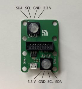
QikEasy i2c Adapter
The i2c Adapter board provides dupont 4-pin sockets on both ends of the board, the diagram below shows the pinout of these sockets.
- The two 4-pin sockets are exactly the same. You should only need to connect to one of these sockets.
- Your i2c device pins must be 3.3v volt compatible.
- If your i2c robot does not provide enough power at the 3.3v pin (you may notice a significant voltage drop at the 3.3v Pin measured at one of the 4-pin dupont socket), you would need to use the microUSB socket to provide more power. Your power source should provide at least 50mA current, while we recommend a source capable of 500mA or more. This is not mandatory if you already have a very powerful 3.3v from your i2c robot.
- If you use the microUSB socket to provide power to the stack, you should not provide power to any of the 3.3V pins (on the 4-pin Dupont sockets) on the QikEasy i2c Adapter board.
- If you use the microUSB socket to provide power to the stack, the Ground of the microUSB must be connected to your robot’s GND pin in the i2c connector. Please ensuring the GND dupont pin is also connected to your robot in addition to SDA and SCL.
Caution:
- Be careful not to mix up your pins. Connecting the wrong pins could potentially blow your QikEasy boards and even your i2c robot circuit board.
- Make sure your i2c robot is 3.3v compatible. Sending 5V to any of the 4 pins on the dupont connector could damage your QikEasy boards permanently.
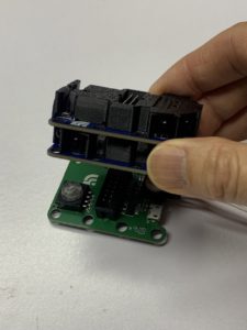
Naming Convention for the First and Second IR Seeker boards
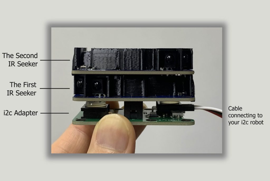
The IR Seeker hardware configuration is very much similar to how you would set it up with QikEasy Expander for Spike Prime, a QikEasy IR Seeker stack consists of a series of boards chained together.
The board connected to your i2c robot is the QikEasy i2c Adapter. After that, the first board (which should be an IR Seeker board) connected to the i2c Adapter board is called the First IR Seeker. If you have another IR Seeker on the stack, this last IR Seeker connected to your First IR Seeker is called the Second IR Seeker. The names are based on the order of the boards in the chain. The connections could be made either through stacking or through the 16-pin cable depending your hardware configuration.
It is important to get familiar with this naming convention as the i2c address of the First and Second IR Seekers will be different based on the positioning. See next section for more details.
How to read Measurements for QikEasy IR Seeker
i2c Address
FIRST QikEasy IR Seeker on the stack: 0x14
SECOND QikEasy IR Seeker on the stack: 0x15
Reading Register Values
0x00-0x07 (8 Characters)
Version String
0x08-0x0F (8 Characters)
Manufacture Name String
0x10-0x17 (8 Characters)
Device Model Name
0x20-0x50
Reserved
0x49 (1-byte unsigned)
IR Ball Direction : return direction value 0 to 9
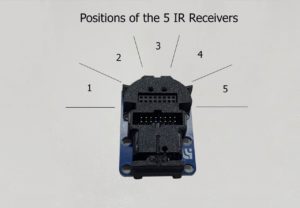
0x4A (2-byte unsigned)
IR Strength detected by IR Receiver #1: range 0 to 1024
0x4C (2-byte unsigned)
IR Strength detected by IR Receiver #2: range 0 to 1024
0x4E (2-byte unsigned)
IR Strength detected by IR Receiver #3: range 0 to 1024
0x50 (2-byte unsigned)
IR Strength detected by IR Receiver #4: range 0 to 1024
0x52 (2-byte unsigned)
IR Strength detected by IR Receiver #5: range 0 to 1024
0x54 (2-byte unsigned)
Maximum IR Strength out of the 5 IR Receivers: range 0 to 1024
Troubleshooting Tips
- Be careful not to mix up your pins. Connecting the wrong pins could potentially blow your QikEasy boards and even your i2c robot circuit board.
- Make sure your i2c robot is 3.3v compatible. Sending 5V to any of the 4 pins on the dupont connector could blow your QikEasy boards.
- Make sure your 3.3V power source is not under powered. If you noticed a significant voltage drop (e.g. if it drops to below 3v) at the 3.3v Pin measured at one of the 4-pin dupont socket, you should definitely look at providing alternate power possibly through the microUSB socket. The minimum requirement is 50mA, but we recommend 500mA.
- If you use the microUSB socket to provide power to the stack, make sure the the GND pin of the 4-pin Dupont i2c connector is connected to your robot along with the SDA and SCL.
- Check the pin numbers used in your program, make sure they match with the actual pins used on your i2c robot circuit board.
- If everything seems correct and you still can’t figure out why your program doesn’t work, you should go back and test with the most basic i2c scanner program first. If your i2c robot runs Adruino, you may look for the scanner in the list of example i2c programs. The scanner should find at least one IR Seeker with the address of 0x14 (or 20 in decimal).
Example
Below is an example code fragment from an Arduino program. (Note that this is NOT the full program. This only contains the parts necessary to demonstration how you may go about using i2c to read the measurements from the IR Seekers.)
#define IR_SEEKER_ADDRESS 0x14
#define REGISTER_DIRECTION 0x49
#define REGISTER_STRENGTH 0x54

void readI2cIrSeeker(int address, uint8_t &dir, uint16_t &strength) {
  // Read 1-byte unsigned data from the "Direction" register
  Wire.beginTransmission(address);
  Wire.write(REGISTER_DIRECTION);
  Wire.endTransmission();

  Wire.requestFrom(address, 1);
  if (Wire.available()) {
    dir = Wire.read();
  }

  // Read 2-byte unsigned data from the "Strength" register
  Wire.beginTransmission(address);
  Wire.write(REGISTER_STRENGTH);
  Wire.endTransmission();

  Wire.requestFrom(address, 2);
  if (Wire.available() >= 2) {
    strength = Wire.read() << 8; // Read the first byte (MSB)
    strength |= Wire.read();               // Read the second byte (LSB)
  }
}


void loop() {
  uint8_t direction1;
  uint16_t strength1;
  readI2cIrSeeker( IR_SEEKER_ADDRESS, direction1, strength1);

  Serial.print("Direction = ");
  Serial.println(direction1);

  Serial.print("Strength = ");
  Serial.println(strength1);

  delay(10);
}